What is a microcontroller, anyway?
A microcontroller is nothing more than a very small, low powered computer on a chip. They are generally small enough to run off no more than the USB power from your laptop, or a few triple-A batteries. They tend to have very little processing power, with clock speeds measuring in the megahertz. Because of their simple instruction set and lower power consumption, they are very useful in applications where something needs be constantly running, whether on wall power or batteries.
Microcontrollers deal with their relative lack of power in several ways. The first is that in general microcontrollers never run an operating system. Code is run directly on the hardware, and only one program at a time is running, giving it complete control over system memory. Because of the need for complete control, microcontroller software is written in C/C++, ensuring that every byte of memory is accounted for, as most microcontrollers only have a few KB of memory. Even though the microcontrollers lack the power of modern day computers or even your phone, because of their durability, versatility, and affordability (around $20 for a whole board), they are frequently used in DIY electronics and art projects.
Most hobbyists don’t use microcontrollers directly. Instead, microcontrollers are generally mounted on printed circuit boards, which make it easy to connect wires by plugging them in or soldering. They also generally have a USB port to allow the chips to be easily reprogrammed from a computer. All of these connections let us connect all sorts of fun devices to our microcontroller, including:
- switches
- buttons
- LEDs
- keypads
- sensors (heat, accelerometer, etc)
- LCD screens
- And much much more more…
What about Wearables?
Wearables have become much more of a trend among arduino enthusiasts with the advent of the modern commercial wearables. In particular, it has become easier and easier to build wearable gadgets, with companies such as Adafruit selling both sewable conductive thread and programmable LED sequins.
Introducing, the Flora!
The Flora is an arduino compatible microcontroller board specifically designed for use in wearables. The first thing to notice about the flora is that rather then using socket headers, which are great for inserting stiff solid-core wire or jumper wires, it provides fat connection plates spaced wide around the board. These connections aren’t very useful for wires, but are excellent for both alligator clips and conductive thread.
Conductive thread is thread that is generally made of steel, and which can be used to stitch traces between components into clothing. There are multiple design features of the Flora that make it easier to use conductive thread with it. The wide spacing on the plates on the flora make it easy to wrap conductive thread around them and tie it off, while avoiding shorting the connectors together. In addition, there are both 3.3V outputs and grounds interspersed throughout the board, meaning that you don’t have to cross over other threads to get power. This is important because the threads themselves don’t have insulation, so cross-overs are basically difficult to impossible.
You’ll also notice one more subtle feature of the Flora that makes it great to use in wearable products, which is that there are no wires poking out the bottom. Even if you’ve never dealt with microcontrollers, you may have seen other printed circuit boards with pokey bits from soldered on chips sticking out the backside. There are reasons why chips are normally manufactured this way, but with the Flora, Adafruit avoided that to prevent it from snagging on clothing or your skin.
Get the Arduino IDE
The use of microcontrollers really took off with the Arduino, which packaged the programming environment and the board in an inexpensive package. We will be using a different board, but it is still based on the same chip and architecture used by Arduino. This also means we can use the same programming environment as well.
You should download the Arduino IDE at https://www.arduino.cc/en/Main/Software, or you can grab one of our USB keys preloaded with it. Installing the IDE should be as simple as unpacking the zip file in which it is packaged and running the program.
Install the Flora drivers
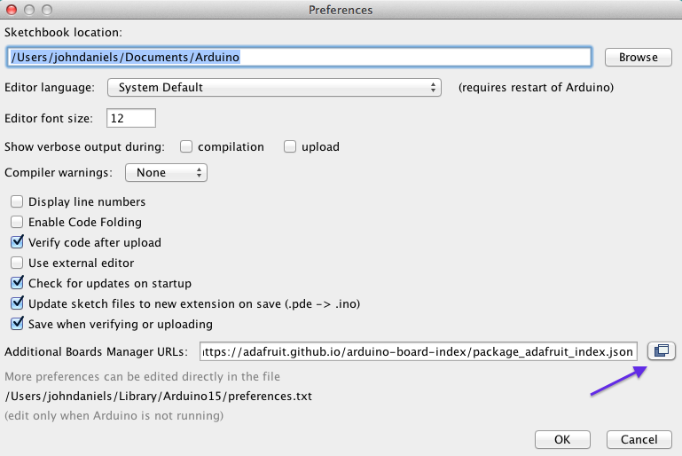
Before we can write or hello world program for the Flora, we first need drivers to upload code to the board. The newest versions of the Arduino IDE make it super easy to install drivers for new devices. In order to do this, you should find the preferences menu (Under “Arduino” on OS X, and “File” for Windows/Linux). Once in the preferences menu, add https://adafruit.github.io/arduino-board-index/package_adafruit_index.json to Additional Boards Manager URLs.
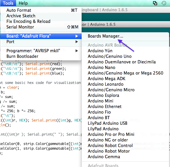
Once that is done go to Tools -> Board -> Boards Manager, and search for “adafruit”. You should see an entry for “Adafruit AVR boards”. Click on it and install it.
Once that is done, close and reopen the Arduino IDE, and you’re ready to start hooking things up.
A basic test project
Our very first hello world will be to make the LED light on the Flora flash on and off. In order to do this, we’re going to create a new “sketch” (basically another name for “program”) in the arduino IDE. If there isn’t already a window open to start coding in, just go to file -> new, and then save your sketch as “blinker”. Once that is done, edit the code to look like the following.
void setup() {
  // put your setup code here, to run once:
}

//LED is always pin 7 on the Flora
#define LED 7

void loop() {
  // put your main code here, to run repeatedly:
  Serial.println("Hello, World!");
  digitalWrite(LED, HIGH);   // turn the LED on (HIGH is the voltage level)
  delay(500);               // wait for 500 milliseconds
  digitalWrite(LED, LOW);    // turn the LED off by making the voltage LOW
  delay(500);               // wait for 500 milliseconds
}
As you’ll see, the arduino environment wants us to implement two functions. The first, setup, is run once when the microcontroller boots up. The second, loop, is run continuously. You can think of it a little like having the following C main function:
int main(void) {
    setup();
    while (true) {
        loop();
    }
}
There are a couple of interesting things to note here. The first is that we simply use the number “7” to represent the LED itself. On the Flora, each connection to the chip is given a number, with different numbers representing different pins. In this case, the number 7 doesn’t represent an external connection, but a pin that is hardwired onto the board as going to the LED. If you look closely at the board, some of the conectors are labeled with numbers such as ‘D6’. In general, these numbers correspond to the number that represents the connector in the programming environment.
The next thing to note is that there are some built in classes and commands in our environment that are useful. The first thing we do in our loop is print “Hello, World!”, on the Serial line. This Serial class corresponds to the serial connection back to the computer when the USB connector is plugged in. You can send any bytes you want to over this connection, but here we are simply sending the bytes corresponding to the string “Hello, World!” You can view the Serial output of the board by going to Tools -> Serial Monitor.
The next builtin function is the digitalWrite function. this function outputs either a high voltage (ON/1/true) or a low voltage (OFF/0/false) on a pin. In this case high/low corresponds to whether the on-board LED should be on or not.
The final useful built-in is the delay function. This simply pauses the code execution for the specified number of milliseconds.
Running the code
Now that we understand what the code should do, we should try running it and seeing if it behaves as expected. The first order of business is to plug a micro-USB cable into your Flora. There should be a green LED that turns on. It is also possible that there is a program pre-loaded onto the Flora that causes the red LED to blink. This is normal.
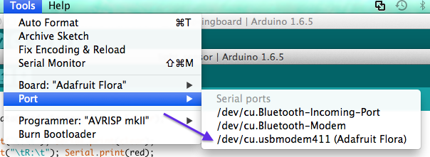
Once the Flora is connected to the computer, we will need to actually perform the code upload. In the Arduino IDE, go to Tools -> Port, and look for the port that mentions the “Adafruit Flora”. It should probably also be the one that makes a reference to ‘USB’ in the name. Once that port is selected, click the Arrow button to upload the code to the Flora. Your computer should compile for a while, and after a pause, the Flora should start running the program.
Let’s do some color
The Flora doesn’t only have an onboard LED. It also has a full color NeoPixel, which is a collection of LEDs that can display any level of brightness and any color. As you can imagine, you can do much more exciting things with color and brighness than with just an on/off LED. We’re going to do some fading of colors.
The first order of business is to install the relevant library to use the NeoPixel. To do this, simply go to sketch -> Include Library -> Manage Libraries and search for and install the Adafruit NeoPixel library. Once that is done, we’re going to start with porting our blinking code to the NeoPixel.
![]()
Type the following code into the arduino IDE, either in a new sketch or in the current one where you wrote the original blinking code.
#include <Adafruit_NeoPixel.h>

// The NeoPixel is on Pin 8 on the Flora
#define PIN 8

// The first parameter represents the number of Neopixels, the second is the pin.
// The third is the format of the data we send it.
Adafruit_NeoPixel strip = Adafruit_NeoPixel(1, PIN, NEO_GRB + NEO_KHZ800);

void setup() {
  // put your setup code here, to run once:
  strip.begin();
  strip.show(); // Initialize all pixels to 'off'
}

void loop() {
  // put your main code here, to run repeatedly:

  //These color values are in RGB, and can go up to 255, but that's way to bright.
  strip.setPixelColor(0, strip.Color(50, 50, 50));
  strip.show();
  delay(500);               // wait for 500 ms
  strip.setPixelColor(0, strip.Color(0, 0, 0));
  strip.show();
  delay(500);               // wait for 500 ms
}
You’ll notice that in this case, we have an actual object, on which we can call methods such as setPixelColor and show, rather than simply writing to a number that represented a particular pin. In this case, the NeoPixel library is hiding all of those details away from us. If you run this code you’ll see the NeoPixel blinking. It’s much brighter than the previous LED, to the point where it’s painful to look at. In this case we only use a brightness value of 50 for each color instead of 255.
But of course, just blinking is boring, so lets add some transitions. Add the following before your loop function:
int red = 50; // Set this to 255 for full strength.
int green = 0;
int blue = 0;
void displayColors() {
  strip.setPixelColor(0, strip.Color(red, green, blue));
  strip.show();
}
This creates global variables to hold the current color, and the displayColors function just displays the color represented by those global variables.
Now, change your loop function to match the following:
void loop() {
  while (red > 0) {
    displayColors();
    red--;
    green++;
    delay(100);
  }
  while (green > 0) {
    displayColors();
    green--;
    blue++;
    delay(100);
  }
  while (blue > 0) {
    displayColors();
    blue--;
    red++;
    delay(100);
  }
}
This updates the colors evert 100ms so that each color fades out to the next one. Now, when you upload the sketch, you should see a light that slowly changes color between red, green, and blue. Take some time and tamper with the pixel color settings in any way you like.
Our other components
For this project we will also be using a few other components. The main one is a color sensor, which is simply a chip that can determine what color is in front of it. The other components are LED sequins, which are little collections of LEDs that can be made to display any color you want.
Wiring up the sensor.
Now we get to wiring up some real hardware. You’ll want to wire SDA to SDA, SCL to SCL, 3V to the 3.3v, and GND (ground)to GND.
The SCL and SDA pins are used to handle serial data. SCL is the clock that sets how fast data transmits and SDA is the actual data line.
Testing the code
In order to test the color sensor we’ll need to install the library for it. Go to Sketch -> Include Library -> Manage Libraries, and search for TCS34725. There should be a matching Adafruit library online that you can install.
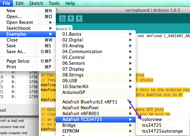
Once you have installed the library, you should be able to run the example program, under File -> examples -> Adafruit TCS34725 -> colorview. Run the program, and open the serial monitor at Tools -> Serial Monitor. The sensor should be outputing RGB color values. You should be able to see the color values change as you put different colored objects in front of it, although this will work best with solid, brightly colored objects.
Setting the onboard neopixel
To get a feel for using our neopixel sequins to match the color sensor, we’re going to start by using the onboard neopixel. Luckily our sample code tries to do something pretty similar with LEDs, it just expects a different interface, but we can tweak our example code to talk to a neopixel instead.
First save the example sketch. This will cause the Arduino IDE to prompt you where to save a copy of the sketch, so that you can have you own separate environment to work in.
Next we’ll need to include the library. We’ve already downloaded it so all you’ll really need to do is include the Adafruit_NeoPixel.h header into your header list so your headers. After adding it, the top headers of your file should look like this:
#include <Wire.h>
#include "Adafruit_TCS34725.h"
#include <Adafruit_NeoPixel.h>
Next, we can delete all the code refering to ‘redpin’, ‘greenpin’, and ‘bluepin’, since we’re not actually using separate wires out to LEDs in our program.
We’re also going to want to set commonAnode to false instead of true. This variable determines whether the program should consider a high voltage value to be ‘on’, or a low voltage value to be ‘on’, which normally depends on the wiring of your LED. Luckily, our Neopixel doesn’t deal with analog signals, so we can just set this value to ‘false’, which means that high values mean high light.
// for a common anode LED, connect the common pin to +5V
// for common cathode, connect the common to ground

// set to false if using a common cathode LED
#define commonAnode false
Now we can add the following lines to create an instance of our NeoPixel class
#define PIN 8

// The first parameter represents the number of Neopixels, the second is the pin.
// The third is the format of the data we send it.
Adafruit_NeoPixel strip = Adafruit_NeoPixel(1, PIN, NEO_GRB + NEO_KHZ800);
You should remember the above code snippet from earlier in the tutorial :)
Also, at the end of your setup function you can add the following lines to make sure the NeoPixel starts and switches its pixels off if they’re not already.
  strip.begin();
  strip.show(); // Initialize all pixels to 'off'
Finally, we need to actually set the colors. Get rid of all the “analogWrite” calls on “redpin”, “bluepin”. and “greenpin” and replace them with the following calls to set the color of our one Neopixel:
  strip.setPixelColor(0,
      strip.Color(gammatable[(int)r], gammatable[(int)g], gammatable[(int)b])
  );
  strip.show();
The main interesting bit here is that we use the “gammatable” computed in the original example code. This exists because the values of R, G, and B that the sensor percieves do not necessarily match the color that would be output if those values were passed directly to LEDs. Instead, the program applies a correction factor to make the brighnesses bettter match.
Phew, that was a lot of changes. After that, your final code should look like the following:
#include <Wire.h>
#include "Adafruit_TCS34725.h"
#include <Adafruit_NeoPixel.h>

// for a common anode LED, connect the common pin to +5V
// for common cathode, connect the common to ground

// set to false if using a common cathode LED
#define commonAnode false

// our RGB -> eye-recognized gamma color
byte gammatable[256];

#define PIN 8

// The first parameter represents the number of Neopixels.
// The second is the pin.
// The third is the format of the data we send it.
Adafruit_NeoPixel strip = Adafruit_NeoPixel(2, PIN, NEO_GRB + NEO_KHZ800);

Adafruit_TCS34725 tcs =
    Adafruit_TCS34725(TCS34725_INTEGRATIONTIME_50MS, TCS34725_GAIN_4X);

void setup() {
  Serial.begin(9600);
  Serial.println("Color View Test!");

  if (tcs.begin()) {
    Serial.println("Found sensor");
  } else {
    Serial.println("No TCS34725 found ... check your connections");
    while (1) {
      Serial.println("busted");
      // halt!
    }
  }

  // thanks PhilB for this gamma table!
  // it helps convert RGB colors to what humans see
  for (int i=0; i<256; i++) {
    float x = i;
    x /= 255;
    x = pow(x, 2.5);
    x *= 255;

    if (commonAnode) {
      gammatable[i] = 255 - x;
    } else {
      gammatable[i] = x;
    }
    //Serial.println(gammatable[i]);
  }

  strip.begin();
  strip.show(); // Initialize all pixels to 'off'
}


void loop() {
  uint16_t clear, red, green, blue;

  delay(60);  // takes 50ms to read

  tcs.getRawData(&red, &green, &blue, &clear);

  Serial.print("C:\t"); Serial.print(clear);
  Serial.print("\tR:\t"); Serial.print(red);
  Serial.print("\tG:\t"); Serial.print(green);
  Serial.print("\tB:\t"); Serial.print(blue);

  // Figure out some basic hex code for visualization
  uint32_t sum = clear;
  float r, g, b;
  r = red; r /= sum;
  g = green; g /= sum;
  b = blue; b /= sum;
  r *= 256; g *= 256; b *= 256;
  Serial.print("\t");
  Serial.print((int)r, HEX);
  Serial.print((int)g, HEX);
  Serial.print((int)b, HEX);
  Serial.println();


  strip.setPixelColor(0,
      strip.Color(gammatable[(int)r], gammatable[(int)g], gammatable[(int)b])
  );
  strip.show();

  delay(200);
}
Now we should can run the app and the color of the pixel on the Flora should match whatever we put in front of the sensor.
Wiring the sequins
The NeoPixel is designed to be wired as a series of pixels, and the sequins are no exception. First chain two sequins along their arrow connectors with alligator clips, starting at pin D6 on the Flora. Then, wire both +s to the VBAtt (this represents the unregulated voltage from the power supply, which is 5V from USB and ~4.5 from batteries), and wire the - leads to GND.
Next change PIN in the code to 6 to indicate that we will be outputing to pin 6, and set the number of pixels in the constructor to 2.
Your code should now look like this:
#define PIN 6

// The first parameter represents the number of Neopixels, the second is the pin.
// The third is the format of the data we send it.
Adafruit_NeoPixel strip = Adafruit_NeoPixel(2, PIN, NEO_GRB + NEO_KHZ800);
You will probably also want to modify the code to update both LEDs, so add another line after you set the first pixel to also set the second pixel at the end of your loop function. The code should now look like the following:
  strip.setPixelColor(0, strip.Color(gammatable[(int)r], gammatable[(int)g], gammatable[(int)b]));
  strip.setPixelColor(1, strip.Color(gammatable[(int)r], gammatable[(int)g], gammatable[(int)b]));
  strip.show();
Sewing to the hat
Now that you have a working electrical circuit, you can turn it into a wearable. The next goal is to emulate that circuit with conductive thread. In order to do this, you’ll need to place the screen on the front of the hat, and the flora positioned on the side of the hat. Then, for each wire from the original prototype, thread the wire through the wire hoop we created earlier, and stitch over to the corresponding plate on the Flora. Next, wrap the thread at least three times around both the hoop and the plate, and then tie it off and cut off any remaining loose thread.
After you stitch each thread, test the circuitry by running your program. That way you’ll know which thread, if any, is problematic. Once all the thread is stitched and all the boards are attached, you can use a battery pack to power the devices for portability.
Link to Adafruit
Congratulations on your hack! if you want more ideas, Adafruit has tons of good example projects as well as documentation for how to implement them. Just go to https://learn.adafruit.com/ to learn more about different wearable and other microcontroller products.